Power regeneration

The efficiency of more than 96%

Regenerative Loads

The economically and ecologically sensible alternative to conventional loads

The new series of electronic DC loads with energy recovery offers new voltage, current and power ratings for a variety of applications. These devices include four common operating modes: constant current, power, voltage and resistance. In addition, the FPGA based control circuit provides additional features such as a function generator, which is simply a table based regulation circuit for the simulation of non-linear internal resistances. Even response times for the control via analogue or digital interfaces have been improved thanks to the DSP controlled hardware. There is one characteristic that despite making the loads applicable to higher power scenarios, it comes with a disadvantage.

Multiple devices in the ELR Series are capable of operating in parallel in a master-slave configuration, which allows the user to parallel the loads for UUTs that might require higher power capabilities. This capability can be extended up to 480 kW in cabinets for a significantly higher total current, with the option to realize higher power capability upon request. However, as power levels to be tested increase, dissipating this energy may not be an attractive option for some customers, as this certainly implies a not so eco-friendly or ‘green’ approach.

The solution implemented in these devices makes the loads to be known as regenerative or energy recovery loads. The most important feature of these electronic loads is that the AC mains connection, i.e. grid connection, is also used as output for the back-feed of the supplied DC energy, which will be converted with an approximate efficiency of up to 96%. Energy recovering allows to lower energy costs and avoid expensive cooling systems, like the ones required for conventional electronic loads, which convert the DC input energy into heat.

YouTube

By loading the video, you agree to YouTube's privacy policy.
Learn more

Load video

Product series ELR with Power regeneration

Principle of Energy Recovery Operation

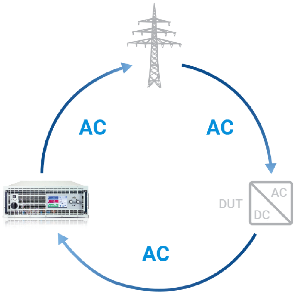
The way a regenerative electronic load operates can be easily explained using figure 1 as a reference. Assume the device under test is a battery cell which consumes roughly 3KW of power. As seen on figure 2, the DC energy becomes an input to a DC-DC converter, which conditions the power so that this one can be processed to the next stage of the conversion.

The last stage of conversion consists of an inverter which transforms the DC energy into appropriate AC energy. By appropriate, it is meant that the AC energy must be conditioned to meet the respective voltage and frequency levels of the local mains.

At this point, the recovered energy is fed-back into the factory grid and it ends up being utilized by the users inside the correspondent industrial or factory premises (in-house grid recovery). In the case the recovered power is higher than the consumed by the users inside the in-house grid, that one ends up consumed by users in the vicinities through the public grid, outside of the premises where the equipment is currently being tested.

It could also occur the factory is not connected to the public grid and, for instance, the load is being used as a device-under-test with a fuel cell. In such case, the ELR Series load limit the recovered power to the one that is consumed solely by the users inside in the inhouse grid. Furthermore, depending on the usage given to the load the equipment could end up paying itself in a few years.

Figure 1: Principle of energy recovery operation.

Figure 2: Power conversion process

Connecting the Electronic DC Load to the Mains

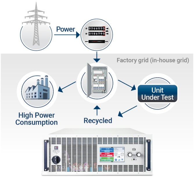
Figure 3 shows the process of energy recovery. In a High Power Consumption production line, we can see an energy recovery load in a testing scenario connected with the Unit Under Test (UUT). The UUT and the ELR regenerative load are connected after the meter and in-line with the main fuse box so the energy recovered is being fed back into the factory grid (in-house grid).

This type of connection must be observed if the unit is to be used as part of continuous test operations. The recovered energy will then be used by production, the lab or even by office equipment.

Figure 3: Recovering energy

Safety Procedures Before Installation and Use

There are several safety procedures before installation and use of the unit and they are as follows: The device may, depending on the model, have a considerable weight. Therefore the proposed location of the equipment (table, cabinet, shelf, 19” rack) must be able to support the weight without restriction.

  • When using a 19” rack, rails suitable for the width of the housing and the weight of the device are to be used. Before connecting to the mains, ensure that the connection is as shown on the product label. Overvoltage on the AC supply can cause equipment damage.
  • For electronic loads: Before connecting a voltage source to the DC input make sure, that the source cannot generate a voltage higher than specified for a particular model or install measures which can prevent damaging the device by overvoltage input
  • For energy recovering electronic loads: Before connecting the AC mains/output to a public grid, it is essential to find out if the operation of this device is allowed at the target location and if it is required to install supervision hardware.

Preparation and mains connection (AC)

An energy-recovery device is connected to the mains via a mains connection cable on the back of the device. In order to connect the unit to the mains, there are several key points that need to be taken into:

  • Connection to an AC mains supply may only be carried out by qualified personnel.
  • Core cross section must be suitable for the maximum input/output current of the device (see table below).
  • Before plugging in the input plug ensure that the device is switched off by its mains switch.
  • Ensure that all regulations for the operation of and connection to the public grid of energy back-feeding equipment have been applied and all necessary conditions have been met.

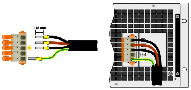
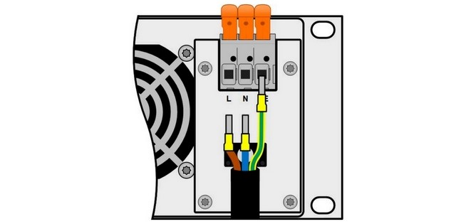
Devices with a height of 2 rack units are equipped with a 3-pole connection terminal (L-N-PE). Larger devices have a 5-pin terminal (L1-L2-L3-N-PE). Depending on the rated power of the device, the plug is connected with two or three phases + PE. In the case of a connection cable with an N conductor, this can be fixed in the free PIN (N) of the connection terminal. The connection cable is to be selected according to the number of wires and cross-section and connected according to the labeling on the terminal. The tables below contain connection data and cross-sections.

The Following Phases are Required for Connection to the Grid (Φ)

Phases L1, L2, L3 N PE
Cross section Imax Cross section Imax Cross section
Rated DC power Inputs on AC plug [mm2] [A] [mm2] [A] [mm2]
5 kW (rated) at 380/400/480 V 3~ (L1, L2, L3, PE)* ≥1,5 16 ≥1,5
3 kW (derated) at 208 V 3~ (L1, L2, L3, PE)* ≥1,5 16 ≥1,5
10 kW (rated) at 380/400/480 V 3~ (L1, L2, L3, PE) ≥4 28 ≥4
6 kW (derated) at 208 V 3~ (L1, L2, L3, PE) ≥4 28 ≥4
15 kW (rated) at 380/400/480 V 3~ (L1, L2, L3, PE) ≥4 28 ≥4
9 kW (derated) at 208 V 3~ (L1, L2, L3, PE) ≥4 28 ≥4
10 kW 3~ (L1, L2, L3, PE) ≥10 40 ≥10
18 kW (derated) at 208 V 3~ (L1, L2, L3, PE) ≥10 61 ≥10
30 kW (rated) at 380/400/480 V 3~ (L1, L2, L3, PE) ≥10 61 ≥10
60 kW (rated) at 380/400/480 V 3~ (L1, L2, L3, PE) ≥16 110 ≥16

* at least L2 & L3

Phases L1, L2, L3 N PE
Cross section Imax Cross section Imax Cross section
Rated DC power Inputs on AC plug [mm2] [A] [mm2] [A] [mm2]
1200 W (derated) at 110/120 V 1~ (L, N, PE) ≥1 11 ≥1 11 ≥1
1500 W (rated) at 208 V 2~ (L, N(L), PE)** ≥1 11 ≥1 11 ≥1
1500 W (rated) at 230 / 240 V 1~ (L, N, PE) ≥1 11 ≥1 11 ≥1
1500 W (derated) at 110/120 V 1~ (L, N, PE) ≥1,5 16 ≥1,5 16 ≥1,5
3000 W (rated) at 208 V 2~ (L, N(L), PE)** ≥1,5 16 ≥1,5 16 ≥1,5
3000 W (rated) at 230 / 240 V 1~ (L, N, PE) ≥1,5 16 ≥1,5 16 ≥1,5

** connect 2nd phase at N terminal

Table 1: Minimum cross-section and maximum current, devices > 2U

Table 2: Minimum cross-section and maximum current, devices in 2U

Figure 4: Example of 4-wire power cord

Figure 5: Example configuration of an AC cable

The longer the connecting cable, the higher the voltage drop due to the cable resistance. If the voltage drop is too high, the load could derive a low voltage error. Therefore, the power cords should be kept as short as possible.